Monday, February 5, 2018

Wise Way for iPhone 6 No Reply

Fault Description:
No series number shows up when dialing *#06#  and kept searching state without signal.
First step is to disassemble the basic, we found  iPhone 6 LCD Screen was replaced ever, we doubt there occurred an Baseband CPU false Welding error, Following our repair process:

From the simple start, measuring the single iPhone 6 motherboard baseband power supply, first measure the main power supply 4.2V (C3221_RF)

                                                                                              14-7-1

Then testing baseband output voltage of power supply on C3262, C3252, C3259, C3256, if there is a voltage without first measuring resistance, if resistance is normal, then replace normal baseband power test; if four of them are simultaneously without resistance, then you need to reinstall the baseband CPU. There is a small glass tube base strip above the baseband power supply, it must be noticed when the main board is disassembled, if it gets damaged, the iPhone 6 will not be repaired.

Before the iPhone 6 CPU is removed, we must deal with the shielding cover carefully. We need to cut it off with professional cell phone repair scissors. This is relatively safe. The shielding factory is very strong in welding, and the risk of heating and blowing is relatively large.

The baseband CPU can be mounted on the fan to avoid heating IC.  It doesn't matter if you see some empty solder points. It takes two parts to solder jumper wire on the pad: U1 and V1 pin.


14-7-2

It may be okay to see two points on the naked eye, but under a Trinocular Stereo Microscope, it will be found that the two points are at the top of the layer, and the line is very thin. Sometimes there will be baseband faults when the line is disconnected. For the sake of insurance, solder jumper wire first.


14-7-3

The small U is thicker. When do CPU reballing, you can cut out a small square on the paper towel and put the small U in it. After installing the baseband CPU, you can first test the C3402_RF to determine whether whether the baseband CPU is installed ok.

After we confirmed it again , boot it. Both baseband and signal shows normal!

Friday, February 2, 2018

Repair iPhone 6 Plus Camera and Fingerprint Inoperation

Fault Description:
iPhone 6 Plus fingerprint and front camera can't work normally same time.
According to the client's words, we knew it has been replaced an iPhone black touch IC. So we doubt the back of component may cause some hurt, okay, let we start our test and repair.

Same problem with the last iPhone, but there an another problem that the fingerprint can't work. And after we open it, we found the touch IC  was replaced ,so we doubt there exist an failure in this component. Let us start the test and repair

First of all, measure the diode data of rear camera adapter with Fluke 15B+ Digital Multimeter, no exceptions found. Then measure the rear camera power supply.
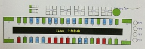
Picture 14-6-1
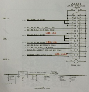
Measure the main camera 1.8V and 1.2V power supply, when we measured the 2.85V power supply, we found that it had no power. Check the iPhone 6 Plus schematic diagram on WUXINJI Dongle to trace the 2.85V source.
Picture 14-6-2

We found that the 2.85V was converted from the main power supply through U2301. During the repair process, short connection A1 and A2 pin can quickly determine if 2.85V power is causing the iPhone camera not working. After short connect A1 and A2 pin, get into IOS to test the iPhone rear camera, it can be turned on now, but short connect 2.85V conversion tube can only test whether it is caused by 2.85V. We can't stop the repairs, because the voltage of PP_VCC_MAIN is 4V, but the power supply of this circuit is 2.85V.
Picture 14-6-3

Direct short connection, take pictures in the darkness, sometimes there are white stripes, you not only can replace the conversion tube here, but also can weld jump wire from the iPhone Nand flash 3V. Generally we weld the jump wire from iPhone Nand flash 3V power supply.
Picture 14-6-4

After finished the welded jump wire, we start to repair fingerprint. First measure the diode data of fingerprint socket. When measured the 12th pin AP_TO_MESA_SPI_MOSI_CONN, its resistance is infinitely large. Trace AP_TO_MESA_SPI_MOSI_CONN signal, we found that it was renamed directly by AP_TOMESA_SPI_MOSI through inductance fl2132. Since there are components in the middle, then we just check FL2132 under the 7-45X 180X Stereo Zoom Microscope 


Picture 14-6-5

Gently wave the components with Precision Titanium Alloy Tweezers, we found it had fallen off. According to iPhone circuit diagram, we know that this inductance is an insurance inductor; the insurance inductor can short-circuit the two pins directly together. When finished, assemble iPhone and test, fingerprints are fine now, the repairs end!


Picture 14-6-6

Thursday, February 1, 2018

Best Way for iPhone 6 WiFi Fault Repair

WiFi question usually will be attention more than other abnormal. The next phone we will repair has the weak WiFi signal which means iPhone 6 Wi-Fi Module can't work normally , we need to find a better solution for this question as we have repaired a similar one. Like the following picture show:


14-5-1

Test whether the main power supply 4.2V has been delivered on C5202_RF, if not, it can be supplied from any place with main power supply, or directly replace WIFI module.


14-5-2

Before disassembly, we need to do some protection to avoid blowing other chips. The WIFI module is surrounded by glue. We must first preheat and remove the glue, and pay attention to small components, especially small resistors. you must to solder it again if some of the components are lost.

The WIFI module on line is relatively thin, do not use solder iron back and forth on iPhone solder pad, testing resistance again after cleaning.

As shown in figure 14-5-3, the lower right-hand corner is easy to break, and the normal is infinite. Therefore, it is necessary to measure whether it is connected to the external connecting elements, if not, it's necessary to solder jumper wire.
14-5-3


There are two kinds of WIFI modules in the market: high temperature and low temperature. We use low temperature and control at about 240 degrees, then install to test the iPhone device. First use the DC power supply to add electricity, Generally if IC involved in the main power supply circuit, do not directly use the battery to boot after replacing IC as to avoid the motherboard burning, after replacing chip, the fault is solved.

If you encounter WIFI can be opened, but only found a small amount of signal, this problem belongs to the WIFI signal, the forty-fifth pin takes main factors, after removing WIFI which can be observed under VGA 7-45X Trinocular Stereo Microscope  .


Wednesday, January 31, 2018

Fast way to fix iPhone 6 camera vertical bar

Now, let we start today's fix work.
This iPhone 6 appears vertical bar question when use this function according to his master said.
Usually we meet this situation, we will check the IC problem. Connecting it with the fluke 15B+  digital multimeter  ,we can see the reality scene from the diode .

Picture 14-4-1

When we measure the diode data for the 34th pin, we found it unstable. Sometimes more than 300, sometimes more than 500 (The normal resistance is about 500). Open WUXINJI Dongle to check iPhone PCB schematic diagram, we know that this pin is 2.85 power supply pin.


Picture 14-4-2

This 2.85 power supply pin is converted from U2301.


Picture 14-1-3

Base on the above conclusions, we suspect that this could be caused by a 2.85V conversion tube virtual weld.  Gently shake the conversion tube with Precision Titanium Alloy Tweezers; The conversion tube has fallen off. We can check it under the VGA Camera 7-45X Trinocular Stereo Microscope.

 
     Picture 14-1-4
The last step is to replace a new conversion tube, we test it after we assembled it well and the data shows normal. Then we boot it, we open the  camera, it shows normally . The repair process ends here.

Tuesday, January 30, 2018

Wise Way to Fix iPhone X Voltage Abnormal

We ever repaired an iPhone X which has the same fault with this one. So we still start the same first step:  test <PP_VDD_MAIN,PP_VDD_BOOST,PP1V8,PP1V1_S2,PP0V8_SOC_FIXED_S1,PP1V8_S2> With the  DC power supply.

After we get the data,we found PP1V1_S2,PP0V8_SOC_FIXED_S1,PP1V8_S2 jumps constantly, so we doubt this may be caused by a power supply circuit of U2700 output. We measured it with digital multimeter, there no other fault appears, it means we should take some other way to diagnosis it.

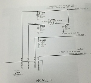
We repaired iPhone 7P before and know that if crystal oscillator is false welding can also cause voltage jumping, And if iPhone CPU power supply is abnormal also can cause voltage jumping. Check the crystal oscillator we find no problem, then check the CPU power supply! As shown in iPhone schemtic diagram 14-3-1 and 14-3-2, there are three ways of power supply, not only directly into the CPU, but also through the small resistance or inductance into the CPU, the three voltage are PP1V2_SOC, PP0V8_SOC_FIXED_S1, PP1V8_IO.


14-3-1


14-3-2

Testing the 3 power supply one by one, when the FL1092 inductor of PP1V8_IO is measured, one end is 1.8V while the other end is 0V.


14-3-3

Testing the end without voltage to the ground dipole value is 490, the normal is about 280. Then testing the inductor's noumenon value is very large, indicating the iPhone X inductor is damaged, so we replace a new inductor, the fault is repaired well.

Later, it was analyzed that the PP1V8_IO was renamed as PP1V8_XTAL after inductance FL1092, which was supplied to the CPU crystal module. It also verified that the voltage jump of iPhone X and the voltage jump of 7P before were actually the same thing.

Hope this iPhone X repair case will help you.

Monday, January 29, 2018

Repair the 4014 Error From iPhone 6S

Got the iPhone 6S which carried the 4014 error , according to the description which comes from its mater, the fault occurred after he flash it and  still kept in the DFU Mode.

After we check the sources fault, we decided to disassemble it to check the iPhone motherboard, the iPhone Nand flash on this motherboard has been repaired, and when check it under the microscope, we can see that the iPhone NAND flash damaged.

Remove the iPhone Nand flash and measure its diode data, it is normal. Put Nand flash into the WL PCIE Nand test programmer to test it, unsurprisingly, the NAND flash is damaged.


Picture 14-2-1
Replace the new iPhone Nand flash and flash it again, the fault still exists. As we know, the iPhone 6S and later iPhone reports iTunes error 4014 mostly caused by nand flash and baseband issues. However, after measuring, we know that the iPhone Nand flash is good, so now the problem is  iPhone baseband. Measure the diode data of baseband power LDO part and S1-S5 power supply, all is normal.


Picture 14-2-2
Flash it again, test the S2 and S4 when the White Apple logo appears, there is no power in either of these places. Since S2 and S4 have no power, it is possible that the baseband power supply does not work and then can't output power. Remove the baseband power, and then use Fluke 15B+ Digital Multimeter to measure it, we found the 55 pin is to ground.


Picture 14-2-3


Picture 14-2-4
55 Pin connected to the 19.2M clock, put iPhone motherboard under the VGA Camera 7-45X Trinocular Stereo Microscope to observe the 19.2M clock.


Picture 14-2-5
19.2M clock with C3501_RF capacitor grounding end connected together


Picture 14-2-6
After we finish the above step, we deal the baseband clock well and then flash it again,  we can see the phone can run normally, the fault disappeared. The repair is success.

Friday, January 26, 2018

Repair iPhone 6SP as Falls Down Heavily

Fault Description:
As of the fall down, it leads to the  iPhone rear camera, Wi-Fi, audio, Phone receptor, card setting etc...
We will repair some function in this repair process.

1-1-1
It can be turned on when using multi-meter to trigger but the current is a bit large. No matter what, we have to turn on the handset and enter into system to have a test.

The first problem is card setting. Continue to test other functions, it is true that the front flex cable, audio key flex cable, and rear camera are all broken, so we have to replace all of the spare parts.

The last fault we need to confirm is motherboard: card setting, bad WiFi, audio recording is not available, bad audio and leakage. Triggered with more than 300 mA current, which means it has problem. Now we should solve the fault one by one.

Since we can't get into the setup, so we take off the iPhone 6s Plus WiFi audio first. The result is the same. There are much solder points are dropped at the bottom of WiFi, it damaged very serious. 30 pin is still on the iPhone 6sp motherboard, but the value is measured with 0L (infinity), certainly it's not normal, so we are going to solder the jumper wire, and also do jumpers on the other disconnected parts.
1-1-2
1-1-3
The jumpers in this repair are easy to do. A tip for new repairman: It's better to leave more jumper outside if there is enough space, so you can extend wire even there are other issues existing.

After soldering jumpers, install the motherboard to test, there is no card setting. We had always thought that only WIFI was not good and that the card was set on the board, and the WIFI would not be stuck. Today, we can see it's same if WiFi is removed off, after install WiFi, the signal is very weak, it seems that the board layer is broken again, direct solder  jumper wire to the opposite track. 
1-1-4
The last step is to change a new iPhone 6P audio IC chip. Then we check some base function, we can see the signal and data flow ,the song also can be played normally. The next repair will be continued next noon.