Wednesday, January 31, 2018

Fast way to fix iPhone 6 camera vertical bar

Now, let we start today's fix work.
This iPhone 6 appears vertical bar question when use this function according to his master said.
Usually we meet this situation, we will check the IC problem. Connecting it with the fluke 15B+  digital multimeter  ,we can see the reality scene from the diode .

Picture 14-4-1

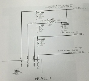
When we measure the diode data for the 34th pin, we found it unstable. Sometimes more than 300, sometimes more than 500 (The normal resistance is about 500). Open WUXINJI Dongle to check iPhone PCB schematic diagram, we know that this pin is 2.85 power supply pin.


Picture 14-4-2

This 2.85 power supply pin is converted from U2301.


Picture 14-1-3

Base on the above conclusions, we suspect that this could be caused by a 2.85V conversion tube virtual weld.  Gently shake the conversion tube with Precision Titanium Alloy Tweezers; The conversion tube has fallen off. We can check it under the VGA Camera 7-45X Trinocular Stereo Microscope.

 
     Picture 14-1-4
The last step is to replace a new conversion tube, we test it after we assembled it well and the data shows normal. Then we boot it, we open the  camera, it shows normally . The repair process ends here.

Tuesday, January 30, 2018

Wise Way to Fix iPhone X Voltage Abnormal

We ever repaired an iPhone X which has the same fault with this one. So we still start the same first step:  test <PP_VDD_MAIN,PP_VDD_BOOST,PP1V8,PP1V1_S2,PP0V8_SOC_FIXED_S1,PP1V8_S2> With the  DC power supply.

After we get the data,we found PP1V1_S2,PP0V8_SOC_FIXED_S1,PP1V8_S2 jumps constantly, so we doubt this may be caused by a power supply circuit of U2700 output. We measured it with digital multimeter, there no other fault appears, it means we should take some other way to diagnosis it.

We repaired iPhone 7P before and know that if crystal oscillator is false welding can also cause voltage jumping, And if iPhone CPU power supply is abnormal also can cause voltage jumping. Check the crystal oscillator we find no problem, then check the CPU power supply! As shown in iPhone schemtic diagram 14-3-1 and 14-3-2, there are three ways of power supply, not only directly into the CPU, but also through the small resistance or inductance into the CPU, the three voltage are PP1V2_SOC, PP0V8_SOC_FIXED_S1, PP1V8_IO.


14-3-1


14-3-2

Testing the 3 power supply one by one, when the FL1092 inductor of PP1V8_IO is measured, one end is 1.8V while the other end is 0V.


14-3-3

Testing the end without voltage to the ground dipole value is 490, the normal is about 280. Then testing the inductor's noumenon value is very large, indicating the iPhone X inductor is damaged, so we replace a new inductor, the fault is repaired well.

Later, it was analyzed that the PP1V8_IO was renamed as PP1V8_XTAL after inductance FL1092, which was supplied to the CPU crystal module. It also verified that the voltage jump of iPhone X and the voltage jump of 7P before were actually the same thing.

Hope this iPhone X repair case will help you.

Monday, January 29, 2018

Repair the 4014 Error From iPhone 6S

Got the iPhone 6S which carried the 4014 error , according to the description which comes from its mater, the fault occurred after he flash it and  still kept in the DFU Mode.

After we check the sources fault, we decided to disassemble it to check the iPhone motherboard, the iPhone Nand flash on this motherboard has been repaired, and when check it under the microscope, we can see that the iPhone NAND flash damaged.

Remove the iPhone Nand flash and measure its diode data, it is normal. Put Nand flash into the WL PCIE Nand test programmer to test it, unsurprisingly, the NAND flash is damaged.


Picture 14-2-1
Replace the new iPhone Nand flash and flash it again, the fault still exists. As we know, the iPhone 6S and later iPhone reports iTunes error 4014 mostly caused by nand flash and baseband issues. However, after measuring, we know that the iPhone Nand flash is good, so now the problem is  iPhone baseband. Measure the diode data of baseband power LDO part and S1-S5 power supply, all is normal.


Picture 14-2-2
Flash it again, test the S2 and S4 when the White Apple logo appears, there is no power in either of these places. Since S2 and S4 have no power, it is possible that the baseband power supply does not work and then can't output power. Remove the baseband power, and then use Fluke 15B+ Digital Multimeter to measure it, we found the 55 pin is to ground.


Picture 14-2-3


Picture 14-2-4
55 Pin connected to the 19.2M clock, put iPhone motherboard under the VGA Camera 7-45X Trinocular Stereo Microscope to observe the 19.2M clock.


Picture 14-2-5
19.2M clock with C3501_RF capacitor grounding end connected together


Picture 14-2-6
After we finish the above step, we deal the baseband clock well and then flash it again,  we can see the phone can run normally, the fault disappeared. The repair is success.

Friday, January 26, 2018

Repair iPhone 6SP as Falls Down Heavily

Fault Description:
As of the fall down, it leads to the  iPhone rear camera, Wi-Fi, audio, Phone receptor, card setting etc...
We will repair some function in this repair process.

1-1-1
It can be turned on when using multi-meter to trigger but the current is a bit large. No matter what, we have to turn on the handset and enter into system to have a test.

The first problem is card setting. Continue to test other functions, it is true that the front flex cable, audio key flex cable, and rear camera are all broken, so we have to replace all of the spare parts.

The last fault we need to confirm is motherboard: card setting, bad WiFi, audio recording is not available, bad audio and leakage. Triggered with more than 300 mA current, which means it has problem. Now we should solve the fault one by one.

Since we can't get into the setup, so we take off the iPhone 6s Plus WiFi audio first. The result is the same. There are much solder points are dropped at the bottom of WiFi, it damaged very serious. 30 pin is still on the iPhone 6sp motherboard, but the value is measured with 0L (infinity), certainly it's not normal, so we are going to solder the jumper wire, and also do jumpers on the other disconnected parts.
1-1-2
1-1-3
The jumpers in this repair are easy to do. A tip for new repairman: It's better to leave more jumper outside if there is enough space, so you can extend wire even there are other issues existing.

After soldering jumpers, install the motherboard to test, there is no card setting. We had always thought that only WIFI was not good and that the card was set on the board, and the WIFI would not be stuck. Today, we can see it's same if WiFi is removed off, after install WiFi, the signal is very weak, it seems that the board layer is broken again, direct solder  jumper wire to the opposite track. 
1-1-4
The last step is to change a new iPhone 6P audio IC chip. Then we check some base function, we can see the signal and data flow ,the song also can be played normally. The next repair will be continued next noon.


Thursday, January 25, 2018

Normal Current While iPhone 6S No Display

Got this iPhone 6S which happens no display but normal current, we doubt the  iPhone PCB Board  may occurred something abnormal. We check it by   DC power supply, of courser, the current and voltage shows normal, but the screen still can't show normal. But during we check it, we found a faint light in the side and the pcb board is very dirty which has some solder flux, we doubt this isn't new phone. We decided to disassemble it.

Now we're going to use Fluke 15B+ Digital Multimeter to measure positive and negative 5.7V on the iPhone display touch power supply tube, the voltage measured is less than 2V. Next to measure the voltage of boost capacitor, the voltage only is less than 2V. Now we know the boost circuit is a problem.

Because the display touch power supply tube has been replaced on iPhone 6S, so we don't need to replace it now, the emphasis is on boosting inductance and capacitance. After measuring the inductance, we found that it was no problem. Then the problem is centered on the capacitor.

Open WUXINJI Dongle to check iPhone schematic diagram, we know this boost capacitance is C4002, we decided to replace the capacitor. With the help of QUICK 861DW, we replace it smoothly and quickly.
Picture 11-7-1

Picture 11-7-2
Assemble the iPhone to test, the screen displays normally now. Continue to test other functions, all is fine, the fault has been solved. The fault is on this small capacitor.

Wednesday, January 24, 2018

Deal Way for iPhone 7P Large Current

Fault Description:
Large current occurred in the iPhone 7P motherboard 
First Step:
Test it with the DC power supply ,then we get a 3.8 V value. We doubt there has a short circuit.
Following the repair process.

11-2-1
Pick up the fault and solve it, then clean it in the water inlet, gently fix the trouble and test the whole function after screen installation, now all other functions are normal, but there is no service on the iPhone 7 Plus.

Observe the radio frequency section under the Trinocular Stereo Microscope  , we find the reception of the front end is corroded.


11-2-2
The fifth trace supply power for RF 1.8V, there is a serious corrosion and the layer is burned, scraping the bottom circuit to solder jumper wire.


11-2-3
It should be noted that this line is the same as a three branch road. If we want to connect the two sides to the bottom and scrape the bottom, if we are not familiar with the circuit, we suggest to scrape up the circuit and check it, then scrape the trouble layer, it's better to carefully do the operation with specialized cell phone repair knife so as to avoid unnecessary troubles.
11-2-4
After we finished the above step , we find a screen connected with this motherboard, we boot it and the screen shows normally, no unstable current produced.  The repair result is success.

Tuesday, January 23, 2018

Process to Repair iPhone 7P Won't Turn On

As of the water damaged, this iPhone 7P can't show normally which half bright and half dark.
The first step ready work is to check the voltage and current, then we will know which failure happened in this phone. 

Repair process

1 After we got the value ,we need to use JM-P01 Essential Toolkit to disassemble the iPhone, remove the iPhone motherboard and then put observe it under the VGA Camera 7-45X Trinocular Stereo Microscope, there has traces of water, and many small original components have been torn down.
 

Picture 10-1-1

2 Connect iPhone motherboard to the computer with C48 MFI USB Cable, there is no response. With the help of YH898D hot air gun and tweezers, we remove the iPhone NAND Flash, and then connect it to computer again, still no response.

3 Use Fluke 15B+ Digital Multimeter to measure the booting power supply and I2C bus, the data is normal. Now we start checking the disconnected iPhone NAND flash that without connecting to the computer. Remove USB tube U4001, measure the resistance of the substrate, we found the E4#(PMU-AOP-TRISTAR-ACTIVE-READY) is short circuit.

4 Open the WUXINJI Dongle to check the iPhone schematic diagram; We can know that this point is connected to the CPU display IC U3703 C2#. So we remove the U3703, and then measure the C2# and U4001 E4# again, the short circuit fault has been resolved.


Picture 10-1-2
The Last Three Steps:
1 Reinstall the  iPhone NAND flash and U4001
2 Replace a good U3703
3 Test the current and voltage 
After we get the normal value, we boot it again and wait for 10 minutes, everything is okay which means the fault was repaired.
Picture 10-1-3

Monday, January 22, 2018

iPhone 6S Boot By itself

With  the intelligence phone development rapidly,  it seems the phone has its own brain. Recently we received an iPhone 6S which can boot by itself, its master said it has been repaired twice . We will be the third shop to repair it, maybe this time is the last time. Let us start the repair process....

After getting the phone, we carefully watched the mobile phone mainboard repair situation, and found that the barometer of the mobile phone was soldered with 4 or 5 jumper wires, but we have no idea what was the fault was fixed at that time.

Observe the iPhone 6s motherboard with a professional Trinocular Stereo Microscope, it is found that there is a small dot near the barometer disappeared. Checking the WUXINJI
 iPhone schematic diagram and bitmap, we get to know it is a zero ohm resistor. 

picture 10-13-1 

picture 10-13-2

picture 10-13-3


After the short connection and installation, the iPhone 6s is tested OK. In order to ensure that the customer will not get any problems when he receives the handset, it will not be a problem if he wait for a night, until the second day morning, we found sometimes it still reboot repeatedly.

Is there a small hole in the barometer that causes a partial damage to the barometer? A barometer is directly found on the dismounted iPhone 6s motherboard, apply high temperature glue on the small hole and blown down the barometer with hot air gun. After the barometer replacement, the iPhone has no reboot failure after waiting for 2 days.

Then we back the iPhone to our customer,  he is so happy we fix it , we like to collect this smile .
But we have some tips sharing: Before you want to repair your iPhone ,please check the problem ,the ensure problem; then find a professional shop team. Or your phone will be hurt again and again and no good result finally.  Especially the part of phone CPU


Friday, January 19, 2018

Effective way to Handle iPhone 6S Fingerprint Failure

Fault Description:
The iPhone 6S can't recognize your fingerprint as of the water damaged.
According to the former experiences, we doubt the short circuit or the touch screen failure.
Following the solve way:

Disassemble the iPhone by JM-P01 Toolkit, carefully remove the iPhone motherboard. After checking, we found signs of corrosion in the fingerprint socket, and then detect MESA_TO_BOOST_EN_CONN.

Use Fluke 15B+ Digital Multimeter to measure the diode data of PP16V5_MESA_CONN fingerprint boost boot signal and 16.5V, the data is normal.

Observe the iPhone PCB board carefully under the VGA Camera 7-45X Trinocular Stereo Microscope, we found something else. The bottom pin was severely corroded after the corrosion was removed from the fingerprint boost U4040. A2 pin PP_VCC_MAIN is disconnected, and the A1 pin CND close to PP_VCC_MAIN is dropped by corrosion.


Picture 10-16-1

Soldering the jump wire on A2 pin via Quick 861DW, but the fault still exists. Why is there such a problem? There are no problems anywhere else, L4040 boost inductance is normal after checking.

We have to rearrange the repair ideas, and then re-check it. Most of the time, we're only one step away from fixing the iPhone, it depends on the details. Open the WUXINJI Dongle to check the iPhone schematic diagram, we found this boost IC bottom pin only has two GND.


Picture 10-16-2

Someone would say, the ground is interlinked, that's definitely not a problem. The iPhone motherboard GND must be connected. However, after measuring, the two ground of IC bottom pin is disconnected, which means these two are indispensable. If one is missing, it will cause U4040 not to work. After weld the jump wire, the problem of fingerprint that don't have 16.5V has been solved.

Install the iPhone and turn on it to test, the fingerprint entry is normal, now you can add fingerprint on your iPhone. Test the other functions, all is fine.

Fingerprint bottom pin GND cannot be ignored, because it can cause U4040 IC not working. During the repair process, you can ignore any place that might cause problems. Just be careful and patient.

Thursday, January 18, 2018

Handle iPhone 6 No Wi-Fi Failure

The customers send an email to us about hers iPhone without Wi-Fi connect , it is the third time she sent to the repair shop . We disassemble it and found lots of solder flux covered on Wi-Fi and the nearby resistor was lost, the bottom of Wi-Fi was scrapped to copper wire. We doubt there exist others failure which caused the Wi-Fi Module problem. Let we start to the check.


First remove the Wi-Fi and boot device to measure the voltage of Wi-Fi  bottom board pin, we find that 14 pin has no signal voltage, it should be 1.8V. The problem comes from here. Using a digital multimeter to measure but no resistance, so we use WUXINJI bitmap to check and find it is directly through CPU, is it the bottom board wire disconnection?

It can be seen from the bitmap 10-25-1 that the iPhone 6 bottom board wire is really disconnected.


Now we have to see if there is another way, continue to look at the principle diagram Apple 6. As shown in picture 10-25-2 and 10-25-3.

This reset signal has a capacitor and a pull-up resistor. The capacitance is next to Wi-Fi . There is no resistance in the measurement. This is hopeless, then we look at the pull-up resistor again, find it is on the back of the iPhone 6 CPU from the bitmap, and it's very close. Measuring resistance is 446, then directly solder jumper wire, install Wi-Fi , but the icon is still gray. Then we think the Wi-Fi  may be broken. Immediately replace a new Wi-Fi  chip, Bluetooth is shown up, Wi-Fi  also appeared, the fault is fixed now!  As shown in Picture 10-25-4:

Tuesday, January 16, 2018

Effective Way to repair Weak iPhone 6P Wi-Fi Signal

No other damaged occurred in this iPhone 6P, the customer said the weak Wi-Fi  bothered him for a long time. So we got it and test it with the multimeter , no abnormal value about current and voltage ,the fault  shown in picture 10-4-1:
Picture 10-4-1

Repair process:
Step 1. Install the iPhone 6P motherboard to test WiFi signal. Obviously, It's weaker than a normal mobile phone.
Picture 10-4-2

Step 2. Remove the motherboard to check, the WiFi connector circuit is not damaged, in many cases, most of repairmen would directly replace the iPhone WiFi IC if WiFi itself gets damaged.

Step 3. Since we have advanced equipment with VGA 7-45X Trinocular Stereo Microscope to do careful observation, the motherboard is very beautiful, there is no water damage trace, the first consideration of fault is pressed parts.

Step 4. Indeed, we can see the IC be pressed under the microscope , of course, do not first think that WiFi itself under pressure, sometimes the next filter will also suffer pressure. The following picture 10-4-1 is pressed IC fl_cell_rf with false welding, also with minor cracks.
picture 10-4-3
Step 5. Take care to remove the IC and the small inductance. Losing inductance will also cause weak WiFi signal, of course, it is also possible to solder jumper wire to solve this kind of situation.

Step 6. Reinstalling IC fl_cell_rf to test WiFi signal, the problem is successfully solved now!